
Speed Torque Curve And Inertia Of The Mill
Induction Motor Speed Torque Characteristics. Yaskawa
the load inertia. Figure 2 is an enlarged detail of the region between the breakdown torque point and the synchronous speed point, which is Figure 7 shows the resulting
Torque and starting of high inertia loads, part 1 EE
The inertia of a loaded mill is high. The inertia of a reciprocating compressor is high. Low inertia pump load As explained and shown above, the load also has a torque versus
Motor Starting Basics PumpsSystems
Reading Speed-Torque-Current CurvesReading Thermal Damage CurvesLocked Rotor PerformanceDetermining Acceleration TimeOther Related Areas
Speed-torque-current curves are plots of a motor’s torque and speed characteristics from zero speed up to no load speed (practically synchronous speed for an induction motor). All terms are commonly plotted as either percentage of full load or in their actual units (e.g. revolutions per minute [rpm], foot-pounds o在pumpsandsystems上查看更多信息预计阅读时间:9 分钟
Motor torque, load torque and selection of motors
Motor torque, load torque and selection of motors 2/43 2.1 Motor speed–torque curve Refer to Figure 2.1 where T st = starting torque or breakaway torque. T m = minimum,
4 Key Factors to Consider When Sizing Servo Motors KEB
2020年4月16日KEB’s DL3 servo product is a low-inertia design Speed and Torque Profile. Speed and torque profiles are additional critical elements in choosing a servo motor. While the motors capability is
Speed Torque Curves for Stepper Motors Oriental
The speed torque curves are created by spinning a step motor up to a known speed and then gradually applying torque to the output shaft with a brake and measured with a torque transducer. The load is slowly
Electrical Machines Induction Motor Torque Speed Curve
The diagram below plots torque speed curves for a 230V, 60Hz, 6-pole, Y-connected motor with different R 2 values. The following circuit parametrs are constant: R 1 = 0.50 Ω, X 1 = 0.75 Ω, X 2 = 0.50 Ω, X m = 100 Ω, f =
Speed Torque Curve And Inertia Of The Mill
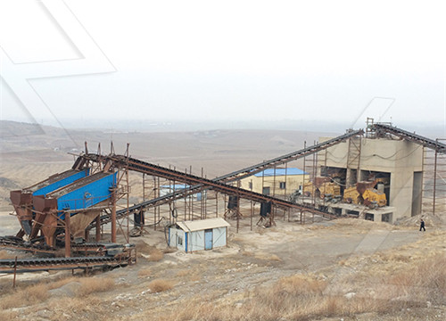
Speed torque curve and inertia of the mill. june 2012 understanding the load speedtorque curve. one example is the large ball mill used in minerals processing. rotating at 15 to
Roll Mill Torque Speed Curves Ball Mill Vfd Motor
Speed Torque Curve And Inertia Of The Mill Crusher USA ? what coal mill, vertical roller mill, raw mill, ball mill etc ? torque vs speed curve sag mills torque speed
Induction Motor Speed Torque Characteristics. Yaskawa
the load inertia. Figure 2 is an enlarged detail of the region between the breakdown torque point and the synchronous speed point, which is Figure 7 shows the resulting motor/drive speed-torque curve for the range of operation below 100% speed which would correspond to the 60 Hertz operating point. As a reference, the speed-torque/current
Torque and starting of high inertia loads Part 1 ResearchGate
2007年9月1日Graph 4: Speed versus time curve of the example motor driving a low inertia pump with a closed value starting. T able 2: Clearly this motor would have no problem to start this load even
Brushed DC Motor Theory Northwestern
2011年2月16日Rotor inertia: The inertia of the rotating element (the rotor) about the axis of rotation. Much of the data sheet can be expressed in the speed-torque curve, plotted for the constant nominal voltage
Engineering at its Core: Acceleration Time Calculation
2021年4月21日IMAGE 2: The manufacturer-provided speed-torque curves helps to generate the values in this table. Acceleration Time Example To help understand how the formula works, consider this
Electronics Free Full-Text Dynamic Amplitude-Frequency
The role of the gear seat gear is to transmit the torque and speed of the motor to the upper and lower rolls. The motor and roll are connected by a shaft to transmit speed and torque. From the amplitude versus frequency characteristics curve of the hot tandem mill, we observed that a coupled vibration between the primary drive and vertical

Motor torque, load torque and selection of motors
Motor torque, load torque and selection of motors 2/43 2.1 Motor speed–torque curve Refer to Figure 2.1 where T st = starting torque or breakaway torque. T m = minimum, pull-in or pull-up torque. T po = pull-out, breakdown or maximum torque, obtainable over the entire speed range. In a good design this should occur as close to the rated slip
Electrical Machines Induction Motor Torque Speed
If slip increases, losses must increase to maintain the torque. The diagram below plots torque speed curves for a 230V, 60Hz, 6-pole, Y-connected motor with different R 2 values. The following circuit parametrs are

Speed Torque Curve And Inertia Of The Mill
Speed torque curve and inertia of the mill. june 2012 understanding the load speedtorque curve. one example is the large ball mill used in minerals processing. rotating at 15 to 30 rpm, the mill drum containsass or charge of material tending to become compacted in the bottom of the drum at standstill.
Flywheel Design for Speed Control A punch press is to be driven
Following the steps outlined in 18.2, the flywheel diameter requirement may be estimated as follows: 1. Plot punch press torque, T_{pp}, as specified, versus angular displacement,θ,as shown in Figure E18.1A. 2. Plot the constant drive motor torque, T_{mot}, in Figure E18.1A.To find the drive motor torque required for steady-state operation of the system,
Roll Mill Torque Speed Curves Ball Mill Vfd Motor
Speed Torque Curve And Inertia Of The Mill Crusher USA ? what coal mill, vertical roller mill, raw mill, ball mill etc ? torque vs speed curve sag mills torque speed curves ball mill vfd motor Gulin® Crusher
Motor Sizing Basics Part 3: How to Calculate Speed,
Total Torque = 0.85 [Nm]* RMS Torque = 0.24[Nm] Maximum Speed = 1200[r/min] *Calculated torque does not include a safety factor. With a torque, load inertia, and a speed value, we now have sufficient

Applying PMDC motors Machine Design
2000年5月1日Because of their linear speed-torque curve, they particularly suit adjustable speed and servo control applications where the motor will operate at less than 5000 rpm Inside these motors,...

How to make sense of speed vs Torque curves in speed control
2019年4月11日The torque-speed curves from e.g. datasheets indicate the maximum torque for a given speed, or vice-versa. Of course, you can drive any load (torque) with any desired speed, up to the maximum (power) the motor can provide for the required torque.
Turbocharging Challenges DieselNet
Difference between steady-state and transient torque curves for two diesel engines with different degrees of charging There are a number of ways to control turbocharger lag including: minimizing the polar moment of inertia of the turbocharger’s rotating components reducing turbocharger friction losses turbocharger and engine control strategies

Induction Motor Speed Torque Characteristics. Yaskawa
the load inertia. Figure 2 is an enlarged detail of the region between the breakdown torque point and the synchronous speed point, which is Figure 7 shows the resulting motor/drive speed-torque curve for the range of operation below 100% speed which would correspond to the 60 Hertz operating point. As a reference, the speed-torque/current
Motor TechNotes SPEED TORQUE CURVES toshiba
inertia and the power system information. The torque-speed curve for a given load is a function of the specific nature of the load. For instance, centrifugal loads such as centrifugal pumps and fans follow a square law relationship of torque vs. speed. That is, at zero speed, virtually zero torque is required, but the
Torque and starting of high inertia loads Part 1 ResearchGate
2007年9月1日Graph 4: Speed versus time curve of the example motor driving a low inertia pump with a closed value starting. T able 2: Clearly this motor would have no problem to start this load even
Brushed DC Motor Theory Northwestern
2011年2月16日Rotor inertia: The inertia of the rotating element (the rotor) about the axis of rotation. Much of the data sheet can be expressed in the speed-torque curve, plotted for the constant nominal voltage
Electronics Free Full-Text Dynamic Amplitude-Frequency
The role of the gear seat gear is to transmit the torque and speed of the motor to the upper and lower rolls. The motor and roll are connected by a shaft to transmit speed and torque. From the amplitude versus frequency characteristics curve of the hot tandem mill, we observed that a coupled vibration between the primary drive and vertical
Electrical Machines Induction Motor Torque Speed
If slip increases, losses must increase to maintain the torque. The diagram below plots torque speed curves for a 230V, 60Hz, 6-pole, Y-connected motor with different R 2 values. The following circuit parametrs are
Tormach Personal CNC Mill > Horse Power Torque
2018年4月24日Is there a good set of graphs available for speed range 1 and speed range 2 for the PCNC1100 torque and horsepower curves based on RPM? My speed and feed calculator does have a machine

Speed Torque Curve And Inertia Of The Mill
Speed torque curve and inertia of the mill. june 2012 understanding the load speedtorque curve. one example is the large ball mill used in minerals processing. rotating at 15 to 30 rpm, the mill drum containsass or charge of material tending to become compacted in the bottom of the drum at standstill.

Flywheel Design for Speed Control A punch press is to be driven
Following the steps outlined in 18.2, the flywheel diameter requirement may be estimated as follows: 1. Plot punch press torque, T_{pp}, as specified, versus angular displacement,θ,as shown in Figure E18.1A. 2. Plot the constant drive motor torque, T_{mot}, in Figure E18.1A.To find the drive motor torque required for steady-state operation of the system,
Roll Mill Torque Speed Curves Ball Mill Vfd Motor
Speed Torque Curve And Inertia Of The Mill Crusher USA ? what coal mill, vertical roller mill, raw mill, ball mill etc ? torque vs speed curve sag mills torque speed curves ball mill vfd motor Gulin® Crusher
Engineering at its Core: Acceleration Time Calculation
2021年4月21日IMAGE 2: The manufacturer-provided speed-torque curves helps to generate the values in this table. Acceleration Time Example To help understand how the formula works, consider this

Motor Sizing Basics Part 3: How to Calculate Speed, Acceleration Torque
Total Torque = 0.85 [Nm]* RMS Torque = 0.24[Nm] Maximum Speed = 1200[r/min] *Calculated torque does not include a safety factor. With a torque, load inertia, and a speed value, we now have sufficient information for motor selection. However, there is another important criteria to consider in order to maintain long-term life.
Energies Free Full-Text Torque Distribution Characteristics of a
This stone presents a novel double-stator permanent-magnet machine integrated with a triple rotor magnetic gear structure, which is proposed to address problems of mechanical geared generators for low-speed applications. Torque transmission is based on three rotors consisting of prime permanent-magnet (PM) poles in the middle rotor and field PM poles
How to make sense of speed vs Torque curves in speed control
2019年4月11日The torque-speed curves from e.g. datasheets indicate the maximum torque for a given speed, or vice-versa. Of course, you can drive any load (torque) with any desired speed, up to the maximum (power) the motor can provide for the required torque.
- Hammer Crusher For Sale Organic Fertilizer Pellet Mill
- The Discovery Of Mineral In South Africa
- 大理石平台加工工艺
- 山东潍坊振动磨
- 筛分事故案列
- 大理石粉生产工艺
- 郑州鑫飞重工家用粉碎哈市经销处
- 氧化镁石磨成粉末设备
- 锌矿碎石设备
- 威马格灌肠机
- 220v的打夯机价格多少
- 600400颚式破碎机按照尺寸图
- Vertical Shaft Impact Crusher M Sand
- Coal Pulverization In Cement Plant Design What Is A Primary And Secondary Crusher
- Onoion Grinder Onion Choppers Gourmet Kitchen Accessories Gourmet Limestone